Shrinkage, Warpage, and Time
InnovMetric and ShapeGrabber help MPC Molder make timely production decisions for auto parts.
As Miniature Precision Components (MPC)’s bread-and-butter products (i.e., PCV valves, connectors, tubing, fittings, fluid reservoirs, filler caps etc.) became commodity items with shrinking profit margins, MPC began offering automakers new products; these include engine covers emblazoned with logotypes. In contrast to nearly all of MPC’s previous output, these are highly styled parts: domed, embossed or fluted. They are what automakers call “appearance” parts: buyers in dealer showrooms check them out.
Since these parts were several times larger than almost anything MPC had done previously, shrinkage and warpage presented new and difficult quality-assurance challenges. To start production on schedule, engineers were forced to make critical tooling and process decisions in too little time with too little data.
By themselves, shrinkage and warpage can easily exceed the entire tolerance budget. The inevitable molding-process variations push parts even farther out of specification. As always with the automakers, time is the essence of the business relationship. MPC allows itself just four weeks after receipt of a mold to start production and submit sample parts.
Dimensions need to be within a tolerance “budget” of +/- 5 mm to accommodate all processes, materials, and tooling variations.
Shrinkage and warpage are dealt with by:
- Changing the moulding process
- Relaxing the part’s tolerances
- Building a cooling fixture
- Modifying the tool that forms the part
Selecting and implementing any of these can easily take four weeks, which leaves no time for further troubleshooting. “Four weeks is the only window we have to tweak and stabilize the molding process,” Clark said, “and we have to cover a lot more than shrinkage and warpage.”
MPC solved its shrinkage and warpage problems using a ShapeGrabber 3D laser scanner and the point-cloud-based inspection software PolyWorks®, from InnovMetric Software. Savvy MPC management turned the solution into a pair of competitive advantages: Faster time to market and a higher degree of quality assurance!
The Challenge
The big difficulty that molders face with shrinkage and warpage is that they have separate causes. Shrinkage is material related; it ranges from 2% to 14% and may vary between resin batches. Warpage is related to cooling and the designer’s use of thick and thin sections. Successfully addressing these dimensional and tolerance challenges requires a lot of analysis and calculation plus years of experience.
Moldmakers start designing a new tool with estimated shrinkage values from the plastic resin’s material safety data sheet (MSDS). To deal with warpage, moldmakers apply their knowledge of gates, vents, and water lines. Yet until a tool is built and run, shrinkage and warpage are only educated guesses.
Touch probing, mold-flow analysis, and photogrammetry fell short
Prior to laser scanning and point-cloud-based inspection, molders had no surface-inspection tools that were both comprehensive and quick. The best available methods were touch probing with a coordinate measuring machine (CMM), mold-flow analysis and photogrammetry. However, these methods all fell short.
Touch probing
Touch probing misses tiny bumps, sags and, as Clark pointed out, “more subtle things like a warpage shift in the pitch of a pair of X and Y points that twists another point out of its Z tolerance.” This is why thoroughly inspecting a surface requires 500,000 three-dimensional (3D) points and sometimes a million or more, rather than the few hundred that touch-probing provides.
Moreover, Clark added, “the CMM takes seven working days to set up a job, two more days to measure, and another five days after that to crunch all the data. Because the CMM is always busy, we may need to wait another seven days to get a place in the queue. So with point-by-point methods, we have at best only two tries to get it right.”
Mold-flow analysis
Mold-flow analysis is computer simulation that predicts how a resin will shrink and warp based on the location and size of the tool’s gates. There are three big drawbacks:
- Nominal dimensions are used rather than actual inspection data from the part; subsequent mold revisions cannot easily be accommodated.
- Predictions of warpage are theoretical and digital only. Moving beyond mold-flow’s virtual realm requires refinements that moldmakers may refuse to provide.
- Like any simulation, mold-flow analyses contain implicit assumptions and numerical values that might not hold up in the real world.
“We need to know what actually happened in the mold, not what was supposed to happen,” said Clark. Mold-flow analysis is also costly—up to $12,000 per tool—and usually consumes two of the allotted four weeks.
Photogrammetry
Photogrammetry is literally measuring with high-resolution photography. Photogrammetry captures surfaces several times larger than laser scanners do, but glued-on targets may be required for alignment. Once the photos are digitized, they can be readily compared with a downloaded CAD file or can be uploaded to a CAD file as a surface patch.
Photogrammetry was tried as an alternative to check fixtures and gauges for engine vacuum harnesses. “The inspection problem is that they are different for each engine,” Clark said. “In the 13 years I have been here, we have bought over a thousand gauges that probably cost a total of $3.5 million. These are black parts so they photograph poorly if at all,” he added, “and we always have issues of ambient light and depth perception in the Z axis.”
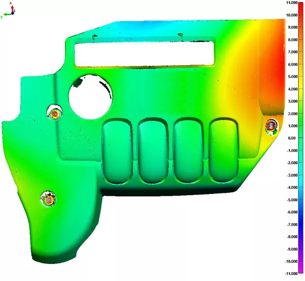
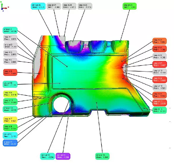
Color map of data-to-CAD comparison
The Solution
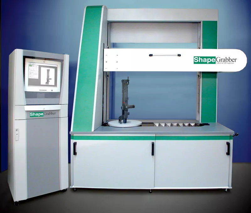
To inspect plastic parts, MPC uses the ShapeGrabber Ai810C scanner. This multi-axis 3D scanner allows the user to request a complete part scan with a single mouse click: the system does the rest.
This ease of use is due to the use of multiple scan axes (horizontal and vertical), as well as a third rotary axis onto which the part is placed. All of these axes are calibrated into the same reference frame, such that multiple scans are automatically aligned. By setting up the required scans for a given part ahead of time, the complete set of scans is easily automated.
The setup process only takes a few minutes due to the very large depth of field (DOF) of the scan heads. This large DOF allows the scans to be set up using a simple and intuitive graphical user interface since it is not necessary to closely follow the complex contour of the part like most other scanners.
The scan heads acquire the data at speeds varying between 18,000 and 150,000 pts/s, so that it only takes a few minutes to generate a complete point cloud representing the part. This data file is then easily processed by PolyWorks|Inspector™ to complete the inspection process.
The combination of speed and ease of use of the scanner makes the scanner accessible to a larger number of users, and reduces the setup and inspection time, drastically reducing the inspection cost compared with alternative methods.
The data that MPC needs is available in 15 minutes—instead of in days
Point-cloud-based inspection in PolyWorks
MPC’s engine cover inspections are now done with full-color maps of tolerances in PolyWorks|Inspector. PolyWorks compares millions of data points obtained by the scanner to the reference CAD model. MPC specialists set tolerances in PolyWorks to determine the acceptable and non-acceptable deviation between data points and CAD model. The display uses the entire color spectrum from red (plus tolerances, too much material) to blue (minus tolerances, too little material). Because the color map’s tolerance band is adjustable, it’s an excellent tool for what-if analyses. “The color maps let us see what is really going on inside the mold, which surfaces are affected by changing a tolerance, and by how much,” Clark explained. “What the color map really shows us,” he added, “is how the plastic part floats inside the mold. We know that the material of the part will shrink into its proper dimensions and the warp during cooling will bring it into the shape its designer called for.”
If MPC engineers need to check something not originally specified in the inspection layout, they just click on the point in the data or add points by rescanning. In either case, it’s just a matter of minutes. In the past, the CMM had to be reprogrammed. “To add even a single touch-probed point, you had to start all over again,” Clark said. “That never takes less than two days.”
For users at MPC and its customers, ShapeGrabber and PolyWorks was the only system that could:
- Keep pace with production rates and inspection frequencies
- Pass standard repeatability and reproducibility (R&R) tests that certify inspection systems
In an R&R test, an operator measures a feature on 10 parts three times. Then a second operator measures the same feature on the same 10 parts three more times and the results are compared. PolyWorks and ShapeGrabber successfully passed these tests.
All the other laser-based approaches were way too slow. None of them could gather the necessary data in less than two or three hours.
“Within minutes, instead of two or three weeks, scanning gives us all the surfaces data we need to choose among the production options,” said Clark. “We get the alignment and formatting from PolyWorks in very close to real time. Finally, we have enough time to make the tough production decisions.” He added, “Because we can gather all the dimensional and tolerance data we need so quickly, we have several additional days to engineer and analyze each job. That extra time is a huge help as we decide whether to seek looser tolerances, modify the tool, change the process in some way, or have a cooling fixture made.”
The time gained also means engineers can go back for a second look. This might include suspect areas in a new batch of sample parts. “ShapeGrabber and PolyWorks help us throughout the entire setup process,” Clark noted.
“We believe MPC achieved a two-week return on investment (R-O-I) with ShapeGrabber and PolyWorks,” he added. “They have given us two new competitive advantages: uncompromising quality assurance and speedy starts on production. With 3D scanning and point-cloud-based inspection, we now have several additional days to make critical business decisions. ShapeGrabber and InnovMetric have helped us throughout the entire setup process, ” explained Gregory Clark.
The Benefits
Succeeding in a demanding new market
The real test of the effectiveness of a new technology is whether its benefits extend beyond the needs of the users in their everyday tasks. In the larger enterprise, those benefits show up in speedier starts for production, more engineering and analysis time, and increased flexibility of methods.
This solution offered:
- Improved quality assurance that helps MPC make sure parts will be molded as required—before samples are submitted to customers.
- Eliminating numerous additional dimensional checks, allowing tools and processes to be locked down sooner for production.
- Increased inspection flexibility, which allows more production options to be evaluated and more time for mold design and tryout; this translates directly into MPC’s new competitive edge—better parts sooner—and happier customers.
- Shortened time to market, while rivals waste days or weeks with touch-probe inspections, MPC gathers 500,000 to a million-plus points on a surface in minutes.
- An enhanced ability to penetrate new markets. MPC moved in one jump from strictly functional, seldom-seen parts to highly stylized, right-in-the-buyer’s-face engine covers.